Lesson 4

Speed sensors

Hall effect, optical encoder, magnetic pickup, tachogenerator.

The basic principle

A speed sensor turns rotational motion into a signal that encodes how fast something is turning. The two strategies you'll see in industry are very different: most sensors count discrete events per second — magnets passing an IC, slots interrupting a light beam, gear teeth disturbing a magnetic field — and then divide by the time taken, while a small group generate an analogue voltage that is directly proportional to rpm.

Pulses vs. analogue
A pulse-style sensor (Hall, optical encoder, variable reluctance) gives a frequency that has to be counted, but the digital signal survives long cable runs and electrical noise far better than an analogue voltage. A tachogenerator gives a voltage you can read with a meter or feed straight into an op-amp circuit, but the analogue signal is more easily corrupted by the environment.
PRINCIPLE
Hall effect
A magnet passes the IC → digital pulse.
Hall ICDigital pulse outputPulses per second = speed
Each magnet (or steel tooth) passing the IC produces one clean pulse.
0:00 / 0:06
1

Hall effect

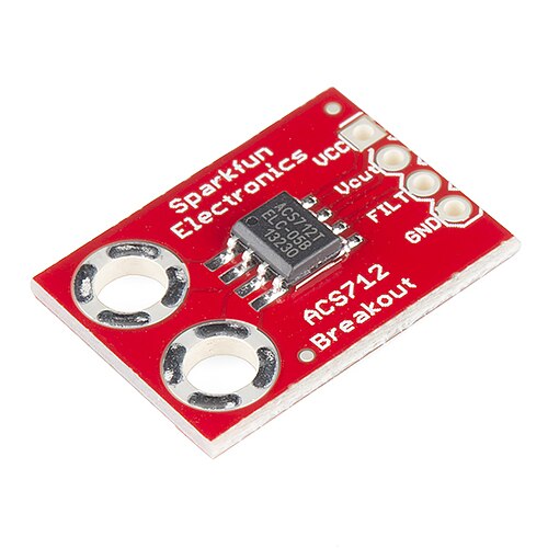
A Hall effect sensor uses a tiny semiconductor chip that produces a voltage whenever a magnetic field passes across it. Inside the chip, current flows through a small slab of doped silicon, and a magnetic field perpendicular to that current pushes the moving charge carriers to one side. The accumulation of charge creates a small voltage across the slab — the Hall voltage — which is amplified into a clean digital pulse.

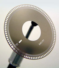
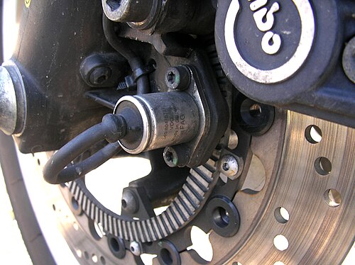
For speed measurement, the sensor is mounted close to a rotating wheel that carries permanent magnets, or, in the toothed-wheel variant, the sensor itself carries a small bias magnet and the rotating wheel has steel teeth. Each time a magnet or a tooth passes the sensor, the field strength at the chip changes sharply, and the chip emits a pulse.

The controller counts pulses over a known time window or measures the time between successive pulses, and from that calculates the shaft speed. Hall sensors are robust, completely contactless, and work all the way down to zero speed — making them the default choice for crankshaft, camshaft, and wheel speed sensing in modern vehicles, as well as for general industrial rotation monitoring.

PRINCIPLE
Optical encoder
Slots chop a light beam.
LEDPhotodiodeBeam interrupts → pulses
A second offset track (quadrature) tells you which way the shaft is turning.
0:00 / 0:06
2

Optical encoder

An optical encoder uses a thin disk with alternating opaque and transparent slots cut around its perimeter, spinning between an LED on one side and a photodiode on the other. As the disk turns, the light beam from the LED is alternately blocked by an opaque segment and allowed through a transparent slot, producing a stream of light pulses at the photodiode.

The electronics convert that stream of pulses into a square-wave digital signal. Each transition corresponds to a known fraction of a revolution — for a disk with one thousand slots, each pulse is one thousandth of a turn — so counting pulses gives both speed and accumulated angle. A simple frequency count over a fixed time window gives rpm; counting up and down gives absolute position.

Most encoders use two photodiodes offset by a quarter of a slot width, producing two pulse trains called A and B that are ninety degrees out of phase. The phase relationship reveals which direction the shaft is turning, while the pulse rate gives speed. This combination of speed, position and direction information makes optical encoders the standard sensor for servo motors, CNC machines, and any application where precise motion control is needed.

PRINCIPLE
Variable reluctance
Teeth disturb a magnetic field.
MagnetCoilAC voltage in coil
Each tooth induces an AC pulse — amplitude grows with shaft speed.
0:00 / 0:06
3

Magnetic pickup (variable reluctance)

A magnetic pickup, more formally a variable reluctance sensor, is a remarkably simple device: a permanent magnet with a coil of wire wound around it, mounted close to a rotating toothed wheel made of ferrous metal. As the wheel turns, the teeth and the gaps between teeth alternately pass in front of the magnet.

When a tooth approaches the magnet, the magnetic circuit through the air gap improves dramatically — the iron in the tooth provides an easier path for the magnetic flux than the surrounding air. As the tooth moves away, the flux drops again. This rapidly changing magnetic flux through the coil induces a small AC voltage according to Faraday's law, producing one cycle of voltage for every tooth that passes.

The amplitude of the induced voltage rises with shaft speed because faster rotation means faster flux changes. The output is a roughly sinusoidal waveform that is conditioned into clean pulses by an external circuit. Variable reluctance sensors are rugged and need no electrical power at the sensor head, which makes them ideal for harsh environments like turbine wheels and gearboxes — but the signal disappears at very low speeds where the flux changes too slowly to induce a usable voltage.

PRINCIPLE
Tachogenerator
A small DC generator on the shaft.
Driven shaftDC voltage ∝ rpm0.00 V
Output voltage is directly proportional to rotational speed.
0:00 / 0:06
4

Tachogenerator

A tachogenerator, often just called a tacho, is a small permanent-magnet DC generator that is mechanically coupled to the shaft whose speed you want to measure. It is structurally identical to a tiny DC motor — permanent magnets in the stator, a wound rotor with a commutator and brushes — but it is being driven by the shaft rather than driving anything itself.

As the shaft turns, the rotor windings move through the stator's magnetic field, and a voltage is induced in those windings exactly as Faraday's law predicts. The commutator and brushes rectify the induced AC into a DC voltage at the terminals. Because the induced voltage is directly proportional to the rate at which the windings cut through the magnetic field, the output DC voltage is directly proportional to the shaft's rotational speed.

A tachogenerator gives you an analogue signal you can read with a meter or feed straight into an analogue control loop without any counting electronics. They were the dominant speed sensor in motor drives and servo systems for decades, and are still common where their simplicity, linearity and instantaneous response outweigh the maintenance of brushes and the bulk of the device.

How to pick one (rule of thumb)
Need precise position as well as speed → optical encoder. Hostile dirty environment → Hall effect or magnetic pickup. Direct analogue speed feedback into an analogue loop → tachogenerator.