Lesson 2

Pressure sensors

Strain gauge, piezoelectric, piezoresistive, capacitive, optical.

The basic principle

A pressure sensor is a device that converts a force-per-area applied to a mechanical element into an electrical signal. In almost every modern sensor that mechanical element is a thin metal or silicon diaphragm that is exposed to the process on one side. Pressure pushes the diaphragm, the diaphragm deflects by a tiny amount, and a sensing element measures that deflection — by a resistance change, a generated charge, a capacitance shift, or a change in reflected light.

Gauge, absolute, differential
Most sensors come in three reference modes. A gauge sensor reads pressure relative to local atmospheric, so it reads zero when open to air. An absolute sensor has a sealed vacuum reference behind the diaphragm and reads pressure relative to a true zero. A differential sensor exposes both sides of the diaphragm to different process ports and reads the difference between them — useful for flow, filter blockage, and level measurement in pressurised vessels.
PRINCIPLE
Strain gauge
Foil stretches with the diaphragm.
Diaphragm + bonded foilResistance R122.7 Ω
Pressure bends the diaphragm → the bonded foil stretches → resistance rises.
0:00 / 0:06
1

Strain gauge

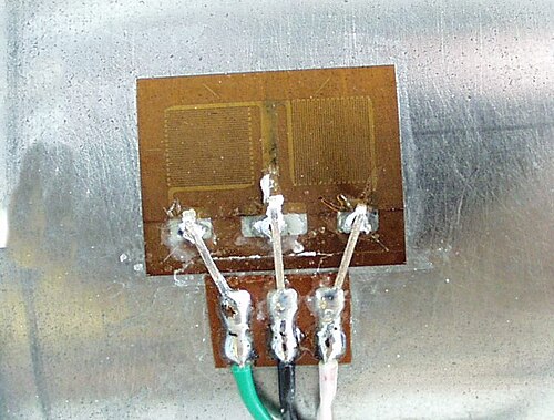
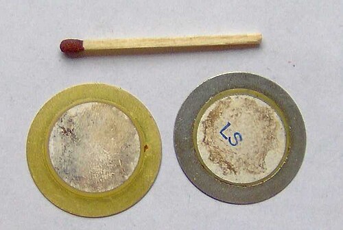
A strain gauge pressure sensor uses the fact that when a metal wire or foil is stretched, its electrical resistance changes. A very thin foil pattern is bonded onto a metal diaphragm with a special adhesive so that the foil moves exactly with the diaphragm.

When pressure is applied, the diaphragm bends inward by a tiny amount — usually a few thousandths of a millimetre. The foil bonded to its surface stretches with it, which lengthens and thins the metal track and increases its resistance. Release the pressure and the diaphragm springs back, the foil relaxes, and the resistance returns to its starting value.

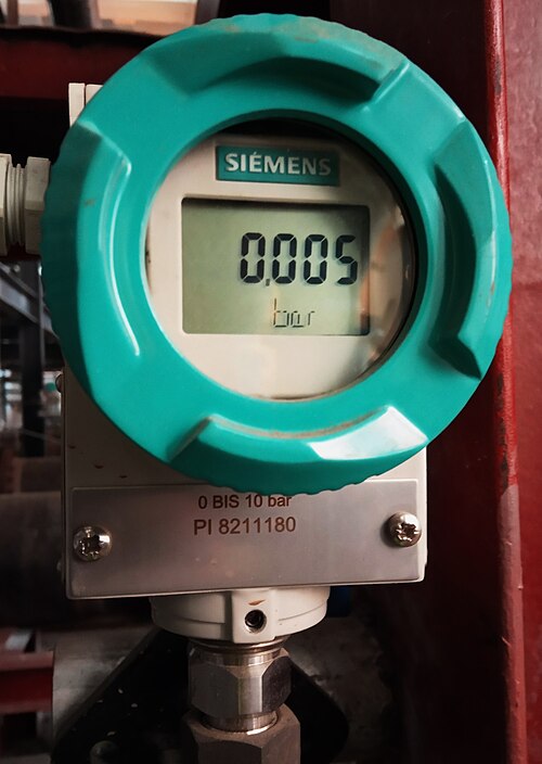
Because the resistance change is small, four gauges are usually wired into a Wheatstone bridge — two stretched in tension, two compressed — and the bridge output is amplified to give a clean voltage proportional to pressure. Strain gauge sensors are robust, work over a wide pressure range, and are the workhorse of industrial pressure measurement.

PRINCIPLE
Piezoelectric
Squeeze a crystal → get a voltage pulse.
Quartz crystalCharge pulse0.00 V
Quartz makes charge under stress — perfect for fast dynamic pressures.
0:00 / 0:06
2

Piezoelectric

A piezoelectric pressure sensor uses a small slab of quartz or specialised ceramic that produces an electrical charge whenever it is mechanically stressed. The crystal is sandwiched between two metal electrodes, with one face exposed to the process pressure either directly or through a thin transmitting diaphragm.

When pressure squeezes the crystal, the atoms in its lattice shift very slightly out of their normal positions and electrons redistribute across the faces. The result is a tiny voltage between the two electrodes that is directly proportional to the force on the crystal. Wires from the electrodes carry that signal to a charge amplifier, which converts it into a usable voltage reading.

The big strength of piezoelectric sensors is speed. They respond to changes within microseconds, which makes them ideal for engine cylinder pressures, ballistic events, blast waves, and other dynamic measurements. The big limitation is that they cannot hold a steady reading: the charge slowly leaks away through the amplifier's input impedance, so they are only used where the pressure is changing.

PRINCIPLE
Piezoresistive
Doped resistors in a silicon diaphragm.
Silicon diaphragmR1R2R3R4R1R2R4R36 mV
Diaphragm stress unbalances the bridge → output millivolts ∝ pressure.
0:00 / 0:06
3

Piezoresistive

A piezoresistive sensor looks superficially like a strain gauge but uses a different physical effect. Instead of stretching a metal foil, it relies on the fact that doped silicon changes its resistance dramatically when it is mechanically stressed. The whole sensor is built on a single small chip of silicon micromachined into a tiny diaphragm with resistors diffused directly into its surface.

When the process applies pressure to one side of the diaphragm, the silicon bows inward and the diffused resistors are stretched or compressed depending on their location. The resistance of stressed silicon changes by a much larger fraction than equivalent metal foil, so the signal is bigger and the sensor can be made much smaller.

The resistors are wired into a Wheatstone bridge on the chip itself, and the bridge output is sent to an amplifier and signal-conditioning circuit, often built into the same package. Piezoresistive sensors dominate consumer electronics and small instrumentation — phone barometers, weather stations, medical devices, automotive manifold pressure sensors — because they are cheap, compact, and accurate.

PRINCIPLE
Capacitive
One plate moves; capacitance changes.
Moving plate (diaphragm)Fixed plateCapacitance ∝ 1 / gap258 pF
Pressure shrinks the gap between the plates → capacitance rises.
0:00 / 0:06
4

Capacitive

A capacitive pressure sensor turns pressure into a change in capacitance — the ability of two conductive surfaces to store electric charge across a gap. The diaphragm itself is one electrode, and a fixed metal plate is mounted just behind it inside the sensor body. Together they form a parallel-plate capacitor with a very small gap between them.

When the process applies pressure, the diaphragm flexes inward and the gap between the two plates becomes slightly smaller. Capacitance is inversely proportional to that gap, so as the plates get closer the capacitance rises. The electronics drive the capacitor with a high-frequency signal, measure the resulting current, and convert the changing capacitance into a voltage proportional to pressure.

Because the change in gap can be made very small relative to the original gap, capacitive sensors can detect tiny pressure changes that other technologies would miss. They are the go-to choice for low-pressure work, vacuum measurement, and differential pressure transmitters in process plants, where their sensitivity and long-term stability outweigh their somewhat higher cost.

PRINCIPLE
Optical
Light bounces off a reflective diaphragm.
Optical fiberReflective diaphragmReflected light92 %
Diaphragm displacement changes the intensity of the reflected light.
0:00 / 0:06
5

Optical (fiber-optic)

An optical pressure sensor uses light instead of electricity to read the diaphragm's movement. Light from an LED or laser travels down an optical fibre to a tiny sensor head, bounces off a reflective surface on the back of a diaphragm, and returns along a second fibre to a photodetector.

When pressure pushes the diaphragm, the distance to the reflector changes by a fraction of a wavelength of light. That tiny movement changes the intensity of the reflected beam, or, in more sophisticated designs, shifts its phase or wavelength. The electronics at the far end of the fibre convert that change into a pressure reading.

Because the sensing element itself is purely optical, there is no electrical signal anywhere near the process. That makes optical sensors immune to electromagnetic interference and inherently safe to use in explosive atmospheres — refineries, chemical plants, fuel tanks — where any spark could be catastrophic. They are also a natural choice for very high temperatures, strong radio environments, and applications where the cabling has to run a long distance through electrically noisy areas.

How to pick one (rule of thumb)
Slow process pressure, robust, cheap → strain gauge or piezoresistive. Very small pressures or vacuum → capacitive. Fast dynamic pressures → piezoelectric. Hostile electrical or hazardous environment → optical.