Lesson 5

Flow sensors

Differential pressure, turbine, magnetic, ultrasonic, Coriolis, vortex.

The basic principle

A flow sensor measures the rate at which a fluid is moving past a point in a pipe. The reading can either be the volume of fluid per unit time — volumetric flow, in litres per second, cubic metres per hour — or the actual mass of fluid per unit time, called mass flow. The technologies you'll meet exploit very different physics — pressure drop, mechanical rotation, electromagnetic induction, the speed of sound, deflection from the Coriolis effect, or rhythmic vortex shedding — and the right choice depends entirely on the fluid and the application.

Volumetric vs. mass flow
Most flow meters give you a volumetric reading. If the fluid density varies — temperature changes, gas instead of liquid, a fuel mixture that shifts in composition — you have to compensate, because the same volume can carry very different masses. Coriolis is the standout exception: it measures mass flow directly, regardless of density, and is the gold standard for custody transfer and chemical batching.
PRINCIPLE
Differential pressure
A restriction drops pressure.
Orifice plateP₁P₂ΔP = P₁ − P₂Q ∝ √ΔP
Squeeze the flow → pressure drops. Flow rate is proportional to √ΔP.
0:00 / 0:06
1

Differential pressure (orifice / venturi / nozzle)

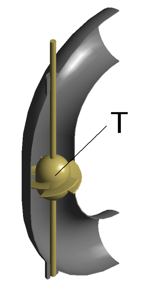
Differential pressure flow measurement is the oldest and still the most common technique in industry. The idea is to deliberately put a restriction in the pipe — an orifice plate, a venturi tube, or a flow nozzle — and measure the pressure drop across it. By Bernoulli's principle, when fluid is forced to squeeze through a smaller cross-section it has to speed up, and as its velocity rises, its static pressure falls.

Two pressure taps are drilled into the pipe wall — one upstream of the restriction and one immediately downstream — and a differential pressure transmitter reads the difference between them. The square root of that pressure difference is directly proportional to the volumetric flow rate, so the transmitter takes the square root and produces a linear flow output.

The technique works with almost any fluid — liquid, gas, or steam — needs no moving parts, and is well understood after a century of practical use. The downsides are the permanent pressure loss across the restriction, the limited turn-down ratio because the relationship is non-linear at low flows, and the maintenance of pressure tappings that can plug with dirty fluids.

PRINCIPLE
Turbine
A free-spinning rotor in the pipe.
Free-spinning rotorPickup
Each blade passing the pickup generates a pulse — frequency tracks flow.
0:00 / 0:06
2

Turbine

A turbine flow meter places a small rotor with several angled blades directly in the flow path inside the pipe. The fluid pushes against the blades and forces the rotor to spin. The rotor is mounted on a frictionless bearing and is balanced so that its rotational speed settles at a value that is very nearly proportional to the average fluid velocity through the pipe.

A pickup mounted in the meter body — usually a magnetic or Hall sensor — detects each blade as it passes and generates one electrical pulse per blade. Counting pulses over a known time window gives the volumetric flow rate, and accumulating pulses gives the total volume that has passed through. The number of pulses per unit volume is a property of the meter, called the K-factor, and is determined by calibration.

Turbines are highly accurate on clean, low-viscosity fluids and are the workhorse of fuel and water custody transfer. The trade-offs are that they cannot tolerate particulates that would damage the bearing or unbalance the rotor, they have a limited turn-down ratio, and at very low flows the rotor stalls before the fluid stops moving.

PRINCIPLE
Magnetic (Faraday)
Conductive fluid + field → voltage.
Coil — magnetic field BElectrodeElectrodeVoltage ∝ velocity0.5 mV
A conductor moving through a field generates voltage (Faraday's law).
0:00 / 0:06
3

Magnetic (Faraday)

A magnetic flow meter — often abbreviated to magmeter — uses Faraday's law of electromagnetic induction. Coils on either side of the pipe generate a magnetic field across the bore, and the fluid itself acts as a moving conductor passing through that field. As any conductor moves through a magnetic field, a voltage is induced across it perpendicular to both the field and the direction of motion.

Two electrodes are mounted in the pipe wall, in contact with the fluid, on the axis perpendicular to the field. The voltage that develops between them is directly proportional to the average velocity of the fluid through the pipe, regardless of the fluid's viscosity or density. Multiply that velocity by the pipe's known cross-sectional area and you have volumetric flow.

The great advantage is that there are no moving parts and no obstruction in the flow path, so pressure drop is essentially zero and there is nothing to wear out or plug up. The crucial limitation is that the fluid must be electrically conductive — water and most aqueous slurries are fine, but oils, hydrocarbons, and gases give no signal at all. Magmeters dominate water treatment, mining slurries, and food processing.

PRINCIPLE
Ultrasonic
Transit-time across the flow.
Tx/Rx ATx/Rx B
The pulse with the flow arrives sooner — the time difference gives velocity.
0:00 / 0:06
4

Ultrasonic

An ultrasonic flow meter measures flow by timing how long a pulse of high-frequency sound takes to travel through the moving fluid. Two transducers are mounted on the pipe, one upstream and one downstream, angled so that each can both transmit and receive. Each takes turns sending a sound pulse diagonally across the pipe to the other.

When the pulse travels with the flow, the fluid's velocity adds to the speed of sound and the pulse arrives slightly sooner. When the pulse travels against the flow, the fluid's velocity subtracts from the speed of sound and the pulse arrives slightly later. The difference between the two transit times — typically only nanoseconds — is precisely proportional to the average flow velocity along the diagonal path.

Because the measurement happens entirely with sound, the transducers can often be clamped to the outside of an existing pipe rather than cut into it, which makes ultrasonic meters ideal for retrofit, temporary measurement, and inspection work. They handle clean liquids and gases well; heavily aerated or particle-laden flows scatter the pulse and degrade the accuracy.

PRINCIPLE
Coriolis
Vibrating tube twists with mass flow.
DriverPhase shift ∝ mass flow
Mass flowing through a vibrating tube twists it — true mass-flow measurement.
0:00 / 0:07
5

Coriolis

A Coriolis flow meter is the only widely-used technology that measures true mass flow directly. The fluid is routed through one or two U-shaped tubes inside the meter body, and an electromagnetic driver vibrates those tubes back and forth at their natural resonant frequency — like a tuning fork.

When fluid is flowing through the vibrating tubes, the inertia of the moving mass produces a Coriolis force that twists each tube. The twist appears as a phase shift between the inlet and outlet halves of the tube: one half leads the vibration cycle, the other lags. Two pickoff sensors at either end of the tube measure that phase difference, and the magnitude of the phase shift is directly proportional to the mass flow rate passing through the tube.

Because the measurement responds to mass rather than volume, the reading is unaffected by density, temperature, viscosity, or fluid composition. The same meter even measures fluid density as a side effect, by reading the change in the tube's resonant frequency as it loads. Coriolis meters are the standard for fiscal metering, custody transfer, and chemical batching where absolute mass accuracy matters more than installed cost.

PRINCIPLE
Vortex shedding
A bluff body sheds alternating vortices.
Bluff bodyVortex sensor
The shedding frequency is proportional to flow velocity.
0:00 / 0:06
6

Vortex (shedding)

A vortex flow meter exploits a phenomenon called the Kármán vortex street. When fluid flows past a blunt obstruction — called a bluff body — set across the pipe, it cannot follow the body's back surface smoothly. Instead, the flow detaches from alternating sides of the body and rolls up into spinning vortices that peel off one side, then the other, in a perfectly regular rhythm.

The frequency at which these vortices shed is directly proportional to the velocity of the flow through the pipe, related by a constant called the Strouhal number that depends only on the shape of the bluff body. A sensor mounted in or just downstream of the body — typically a piezoelectric crystal that responds to the pressure pulses, or an ultrasonic detector — picks up each vortex as it forms and converts the shedding frequency into a flow reading.

Vortex meters have no moving parts, work on liquid, gas and steam, and need very little maintenance. The flow must be high enough to sustain a clean vortex street, which gives them a moderate minimum flow rate, but above that they are accurate, reliable, and widely used on steam lines, condensate, and process gases.

How to pick one (rule of thumb)
Cheap and battle-tested → differential pressure. Clean liquid, accurate batch totals → turbine. Conductive liquids, slurries, waste → magnetic. Non-intrusive retrofit → ultrasonic. True mass flow / custody transfer → Coriolis. Steam, gas, robust → vortex.